logo

TODDY STYLE – HEADQUARTER
Sidemount-Explorer UG
Glasbergweg 7a
79822 Titisse-Neustadt (DE)
Cell: 0049 – (0)178-9313591
www.toddy-style.com

Equipment: oliver@toddy-style.com
Training: toddy@toddy-style.com

Follow us

5. Attaching Scuba Cylinders

The Toddy-Style sidemount system is designed for attaching scuba tanks to the sides of the diver (sidemount configuration). It is not intended and tested for the use of backmount (backmount configuration) and therefore should never be used for this purpose.

There are several variants of the sidemount configuration with regard to the bottles used and their further equipping of the 1st stage, hoses, etc., which also refer to the operation and the procedures during use. Put simply, the Toddy-Style sidemount system can be used with all variants without restriction.

However, in the development of our system, a particular configuration has evolved that has proven to be universally applicable and best suited to our many applications during the development phase. This configuration is presented below as a recommendation.

To take full advantage of the sidemount configuration, the diver should, if possible, set it up so that the scuba tanks can be placed directly in the water or immediately in front of it. Avoid covering longer distances with bottles attached.


5.1 Attaching the Top

As an upper attachment point, we recommend wrapping the neck of the bottle below the cylinder valve with the sidemount bungee on the TS system.

The sidemount bungee is guided directly from the back around the outside of the bottle neck, the outgoing hoses of the 1st stage are not enclosed by the bungee. Then the bungee is fixed to the chest D-ring of the respective side with the carabiner attached to the end. It should be a close-fitting position of the dive bottle can be achieved with the valve handle points forward / outside.

When installed, the cylinder valve should be positioned below, or slightly behind, the armpit, and accessible at any time with both the right and the left hand.

5.2 Attaching the Bottom

There are 3 different attachment points available for bolt snaps on the scuba tanks on the TS system.

1.  The flat mounting straps on the back low profile buttpad. This point is particularly suitable for heavier steel tanks, or for several tanks per side.

2.The Asymmetric D-Ring attached to the waistbelt at the rear under the wing. These points allow a lateral position of the scuba tank parallel to the body of the diver, especially for smaller or lighter scuba tanks.

3. The low-profile D-rings attached to the front of the waist strap. This position can be used if the sidemount tank becomes positively buoyant on the bottom of the bottle. For example, when the pressure of an aluminum tank falls below a certain level, or with light gas mixtures with high helium content (Trimix).

It may be necessary in the course of a dive to change the lower attachment point of the scuba tanks in order account for the consumed gas and the associated trim change of the scuba tanks.

Example:

Begin the dive with 2x 80 cuft aluminum bottles, filled with air 200 bar.

Lower attachment point: Asymmetrical D-Ring (attachment point 2)

After emptying the bottles to about 120 bar, the bottle bottoms get a noticeable boost, the bottle rises at the back.

Therefore change from the asymmetrical d-ring (point 2) to the low-profile D-ring (point 1) until the end of the dive.

In any case, the diver should try to achieve a close-fitting and body-parallel position of the sidemount tanks by selecting the appropriate

attachment. Only then can the streamlined advantages of the sidemount configuration be fully utilized.

The Toddy-Style sidemount system offers perfect mounting options for every configuration with its choices and sophisticated solutions. To fully understand and exploit the potential of the TS system, we strongly recommend a course or qualified training with a familiar instructor. Especially for this purpose there is the TS-sidemount course program of IANTD

,,

The design was frankly, brilliant. It was also rugged and easy to disassemble

,,

Habe schon vieles gesehen und getestet aber das überzeugt mich

,,

Really no kidding, this is the best system I ever used!!!! And the quality is amazing.

5.3 Tank Rigging:

In addition to operating the components of the TS sidemount system, bottle rigging also plays an important role in achieving the bottle position described in the previous section.

1.  Valves: we recommend the use of similar standard valves for both sides. This has the advantage that all bottles used are interchangeable at any time. The TS sidemount system does not require a special combination of right / left valves.

However, all other valve configurations can also be used with the attachment method described above.

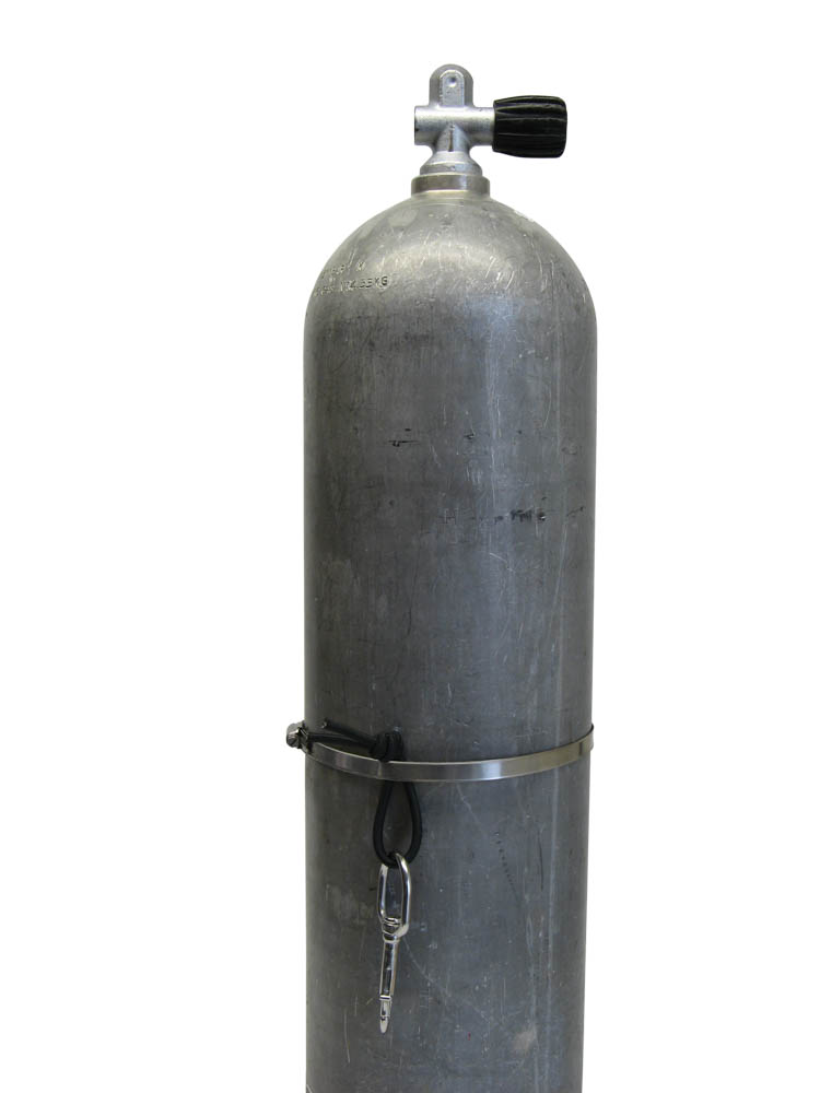
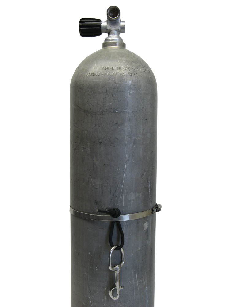
2.Bottom mounting point: We recommend mounting using the TS – Rigging Kit (available as an accessory) which consists of 2 swivel-eye bolt snaps with a big eye and 2 pieces of 6mm rubber rope as well as 2 stainless steel clamps. The delivered diameter can be for the most usual use sidemount bottles (diameter of 170-190mm).

The clamp is placed around the bottle body and tightened with a flat head screwdriver that only a finger’s margin remains. The rubber cord is first pulled through the eye of the bolt snap to form a loop. At the end of the loop, a simple overhand knot is formed, thereby securing the loop. Now, the knot is pushed through from below between clamp and bottle body. Tighten the clamp until there is light tension. Now the clamp can be pushed to the correct position with bungee and bolt snap.

LEFT SIDE

RIGHT SIDE

The Proven Starting Position:

– The clamp should be about 35 cm from the bottom of the bottle.

Position of the clamping screw: opposite the valve handle.

Left tank: Position the bungee and swivel-eye bolt snap on the back side of the tank (opposite mouth of valve)

– Right tank: Position the bungee and swivel-eye bolt snap on the front side of the tank (directly under mouth of valve).

Tighten until the position is sufficiently fixed. A strong pull on the bolt snap should not change the position.

Overhanging sharp-edged ends of the clamp must be shortened and edges covered in order to avoid risk of injury.

The position of the lower attachment point of the dive tank is dependent on the constitution of the diver (upper body length, body circumference, etc.), therefore, this information is only a starting point for a “configuration dive” in a controlled environment. In an individual adaptation dive, these positions must be checked and, if necessary, modified.

These components, as well as scuba tanks, are not part of the TS sidemount system and are not included. For the sake of completeness, our recommendations for a well-suited configuration are presented here.

3. 1. Regulators :We recommend selecting a first stage with parallel, straight down tube connections. Angled or lateral outlets are more exposed to the bottle, and carry a higher risk of damage to the hose connections or entanglement when diving with a guide line (cave diving).

4. Pressure Gauge :We recommend lowering the pressure gauge parallel to the bottle and securing it to the bottle shoulder with a rubber band. Ideal are short gauge tubes between 15 and 20 cm in length.

5. Inflator Hose :We recommend a hose length of 60-65 cm on both sides. The Wing is supplied by the left tank, if a dry suit is used, it can be supplied from the right bottle. The hose guide is as follows:

Left Side (The Wing) :

Coming from the 1st stage pushed from below between body of the diver and the tank bungee, then from behind over the shoulder parallel to corrugated tube under the double bungee to the connection of the inflator head.

Right Side (The Drysuit) :

From the 1st stage through the bungee loop on the right shoulder strap and connect to the inlet valve of the dry suit.

When doing so, the hose should be tightly guided from the inlet valve to the bungee loop. The remaining hose length should now be in an arc between the body of the diver and the scuba tank.

6. Regulator Hose

We recommend a hose length of 100 cm for both sides.

Hose Routing Left Side:

From the 1st stage under the armpit, behind the head to the right and to the mouth. When switching to the other regulator, the first stage of the left bottle is secured in the chest D-ring on the right side.

Hose Routing Right Side

From the first stage diagonally in front of the body, around from the left behind the head to then reach the mouth from the right. When switching to the other regulator, the first stage and hose are brought back completely behind the head and secured on the chest D-ring on the left side. The regulator hose is then pushed in a large arc under the abdominal belt, so that it fits tightly against the body.

The exact use of this bottle / hose / regulator configuration is not a mandatory requirement for using the Toddy-Style sidemount system.

Alternative concepts can also be used, but we would like to point out that their use also has an impact on the security of the application.

They should be thoroughly tested before use, and used in conjunction with appropriate training, or the training of an experienced instructor.

The illustrations in this manual are not intended to replace a single course!